
“UML vs BPMN explained with definitions, benefits, steps, examples, and future trends to help you choose the right diagram for real-world projects.”
✨ Introduction: UML or BPMN — Which Should You Pick?
Have you ever started documenting a project and wondered,
“Should I use a UML use-case diagram or a BPMN swimlane chart?”
You’re not alone!
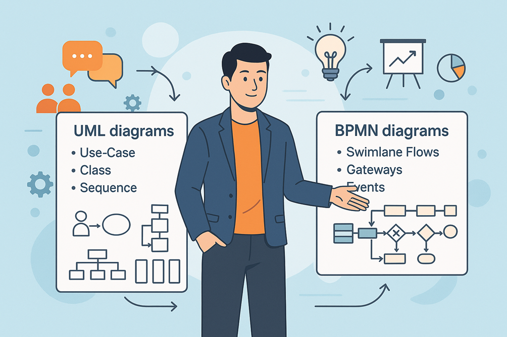
UML (Unified Modeling Language) and BPMN (Business Process Model and Notation) are two of the most popular diagramming languages used by Business Analysts, Product Owners, and Solution Architects.
Choosing the right one at the right time:
- Prevents miscommunication between business and technical teams
- Saves hours of rework
- Makes documentation easier to understand
This blog will help you understand when and how to use UML vs BPMN in your real-world projects.
📝 Section 1: Understanding UML — Unified Modeling Language
📘 Definition
UML is a standardized visual language for modeling the structure and behavior of software systems.
It was created by the Object Management Group (OMG) and is widely used in software engineering and system design.
🔑 Purpose
UML answers the question:
“How will the system be built and how will its components interact?”
It’s most valuable for:
- Describing system architecture
- Modeling classes, objects, and their relationships
- Showing data flow, states, and interactions
🔥 Popular UML Diagram Types
| Category | Diagram Type | When to Use |
| Structural | Class Diagram | Define entities & relationships |
| Component Diagram | Show modules and interfaces | |
| Behavioral | Use-Case Diagram | Capture user goals and system boundaries |
| Sequence Diagram | Show message flow between components/users | |
| State Machine Diagram | Represent state changes of an object |
📌 Static Insight:
UML is technology-agnostic but is often favored by developers and architects for its ability to explain software structure and data flow
📝 Section 2: Understanding BPMN — Business Process Model and Notation
📘 Definition
BPMN is a graphical notation specifically designed to represent business workflows and processes.
Also standardized by OMG, BPMN is business-friendly, focusing on “how work gets done”.
🔑 Purpose
BPMN answers the question:
“What steps does the business process follow from start to finish?”
It’s best for:
- Mapping end-to-end workflows
- Highlighting handoffs between departments
- Identifying bottlenecks and optimization opportunities
🔥 Key BPMN Elements
| Element | Symbol | Usage |
| Start / End | Circle / Bold Circle | Entry and exit points of the process |
| Activities/Tasks | Rounded Rectangles | Steps performed by actors |
| Gateways | Diamonds | Decision points (Yes/No, parallel branches) |
| Events | Double Circles | Messages, timers, or signals triggering steps |
| Swimlanes | Horizontal Bands | Show responsibilities of different actors |
💡 Static Insight:
BPMN diagrams are easier for non-technical stakeholders to read compared to UML because they focus on business flow, not code logic
🔎 Section 3: UML vs BPMN — A Side-by-Side Comparison
| Feature | UML | BPMN |
| Focus | Software/system design | Business process flows |
| Audience | Developers, architects, QA teams | Business users, BAs, process owners |
| Notation | 14 diagram types | 4 main diagram categories |
| Complexity | Technical, detailed | Business-oriented, intuitive |
| Best For | Modeling how the system works | Mapping how the work flows |
| Typical Deliverable | Class, Sequence, Use-Case diagrams | Swimlane diagrams, flowcharts |
💡 Rule of Thumb:
Use UML for system behavior and technical design, and BPMN for high-level workflows and stakeholder discussions.
🌟 Section 4: Benefits of Using the Right Diagram at the Right Time
| Benefit | Why It Matters |
| Clarity in Communication | Visuals speak louder than words |
| Stakeholder Alignment | BPMN simplifies business understanding |
| Better Handoff to Dev Teams | UML diagrams translate business goals to code |
| Reduced Rework | Right diagram prevents misinterpretation |
| Improved Documentation | Visual artifacts stay useful throughout SDLC |
🪜 Section 5: Step-by-Step Guide to Choosing the Right Diagram
Step 1: Identify Your Audience
- If explaining workflows to business leaders → use BPMN
- If discussing system interactions with devs → use UML
Step 2: Define Your Objective
- Want to optimize processes → choose BPMN
- Want to design a new software component → choose UML
Step 3: Select the Diagram Type
- For requirements gathering: Use Use-Case Diagram (UML) + BPMN swimlanes for clarity
- For development discussions: Use Sequence or Class Diagram (UML)
Step 4: Use the Right Tool
- For UML: Lucidchart, Draw.io, Visual Paradigm, Enterprise Architect
- For BPMN: Miro, Signavio, Bizagi, Camunda Modeler
Step 5: Keep Diagrams Simple
- Limit the number of symbols
- Use clear labels and color codes for readability
Step 6: Validate with Stakeholders
- Review BPMN diagrams with business users
- Review UML diagrams with devs and testers
🔗 Section 6: Real-World Use-Case Example
Scenario: Loan Approval in a Fintech Company
- BPMN Diagram: Used to visualize the customer journey — application, document upload, verification, approval.
- UML Use-Case Diagram: Shows how customers, loan officers, and backend systems interact with the loan application software.
- UML Sequence Diagram: Details the order of API calls when documents are validated.
👉 Takeaway: Both diagrams are complementary — start with BPMN for process flow, then use UML to define system details
🛠️ Section 7: Recommended Tools & Their Adoption
| Tool | Type | Usage |
| Lucidchart | UML/BPMN | Browser-based, easy collaboration |
| Visual Paradigm | UML | Rich features for architecture diagrams |
| Camunda Modeler | BPMN | Ideal for workflow automation projects |
| Bizagi Modeler | BPMN | Great for business-centric process maps |
| Draw.io (diagrams.net) | UML/BPMN | Free and versatile |
🚀 Section 8: Future Trends — UML & BPMN in the AI-Driven World
- AI-Assisted Diagram Generation: Tools like Miro AI will auto-suggest process flows.
- AR/VR-Enabled Workshops: Virtual reality for interactive workflow sessions.
- Integrated DevOps Pipelines: UML sequence diagrams auto-generated from code.
- BPMN-to-Automation Engines: BPMN flows feeding directly into RPA tools.
⚡ Insight: By 2026, more than 60% of enterprises will integrate BPMN diagrams directly into workflow automation platforms
📝 Section 9: Quick Checklist for BAs & PMs
✅ Use BPMN for workflows → process clarity
✅ Use UML for system design → technical accuracy
✅ Don’t mix symbols unnecessarily
✅ Always validate diagrams with the target audience
✅ Keep artifacts updated during Agile sprints
🏆 Key Takeaways
- BPMN = What work gets done | UML = How the system works
- Using the right diagram improves alignment, reduces rework, and boosts delivery speed.
- Both are complementary — start with BPMN to understand the business process, then move to UML for implementation details.
💬 Conclusion: Choose Smartly, Deliver Confidently
The debate between UML and BPMN isn’t about which is better — it’s about using the right tool for the right job.
A skilled BA knows:
- BPMN wins at simplifying complex workflows for stakeholders.
- UML shines at bridging the gap with architects and developers.
👉 Start your next project by asking:
“Am I explaining the process or the system?” Your answer will tell you which diagram to draw first